Archives
Chiral Molecule Scattering Experiments
|
Goal In order to investigate these discrepancies between theory and experiment, we will systematically vary three parameters within the target molecules: Z, η, and L, where η is a parameter used to gauge the "degree of chirality" of the target molecules, and L is the distance between Z and the molecule's chiral center. 1. Holding η and L constant, we will vary Z by looking at the series [M(hfacac)3] where M = Fe, Ru, and Os (hfacac = hexafluoracetylacetonate). See the "propellers" in Figure a below. This series has roughly an order of magnitude variation in Z2. 2. To vary η we will compare [M(hfacac)3] with [M(hfc)3], which has a different structure around the central atom. The [X(hfc)3] molecules used by Kessler's group have chiral ligands arranged in a "propeller" fashion around the central heavy atom. The target samples they used, however, comprised a racemic mixture of both right- and left-handed propeller arrangements. Thus the net chirality of the target is limited to its ligands, which are removed from the high-Z atom. Our [M(hfacac)3] molecules, on the other hand, have achiral ligands but will be synthesized with only one handedness of propeller structure. This will place the high-Z atom directly at the target's chiral center. 3. We will vary L by using derivatives of camphor like the type shown below in Figure b. The number n of (CH2) groups will be changed from 1 to 3, increasing the distance between the heavy atom and the chiral center without significantly altering η. 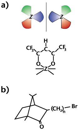
Here is a schematic diagram of the apparatus we use to search for electron circular dichroism in chiral molecules (click on the picture for an interactive view): 
Interactive look | Larger view (static)
Very briefly, a GaAs crystal can be used as a source of polarized electrons if alternating layers of cesium and oxygen are adsorbed onto the surface to create negative electron affinity. Shining circularly polarized laser light (we use 785nm) onto the surface not only gives sufficient energy to electrons in the crystal to excite them into the vacuum, but it also provides angular momentum which aligns the electron spins perpendicular to the surface of the crystal. Extracting the electrons with cylindrical lenses at positive voltage creates a beam of polarized electrons.
A linear polarizer, quarter-wave plate, and a photoelastic modulator (PEM) are placed in the path of the laser beam to circularize its polarization and to modulate the polarization between right- and left-circular states. This in turn modulates the electron helicity between positive to negative states. Then, when the electron beam experiences dichroism upon collision with the chiral target, a modulation of electron current is measured by a lock-in amplifier referenced to the PEM modulation frequency. For most applications, a quarter-wave plate is not used, and linearly polarized light enters the PEM (at quarter-wave retardance) to give modulation of circularly polarized light at 50kHz. However, we have found that in such an arrangement two artifacts of the PEM contaminate our 50kHz signal: (1) lateral beam shift and (2) interference caused by internal reflection. These unwanted signals are predominantly 1st harmonic effects of the PEM. To minimize these problems, we set the PEM to half-wave retardance and inject circularly polarized light. This technique modulates the circular polarization at 100kHz rather than 50kHz. Therefore, we reference our lock-in amplifier to the PEM's 2nd harmonic in order to measure the proper chiral asymmetry. The most difficult task in carrying out this experiment is to achieve instrumental asymmetries below the level of the chiral asymmetries we wish to measure. To do so, we have essentially rebuilt our old apparatus. The new version works much more reliably in the sense that long GaAs crystal lifetimes and high beam currents on target are now obtained routinely. Our overall instrumental asymmetry with the new lock-in detection system is now better than 10-4, and measurements with this precision can now be made in a matter of seconds. (The previous electron counting system required many-hour accumulation times.) The instrumental asymmetry of our optical system alone is about five parts per million. Although we can surely detect chiral asymmetries on the order of 10-4 with our present situation, we would like to improve the overall instrumental asymmetry to the parts per million regime. We are presently preparing to inject bromocamphor into our target cell and reproduce Kessler's results as a preliminary check of our detection scheme. After doing so, we will move on to the series of molecules mentioned above.
|
||||
|
Archived: January 2020 |
